Define Pipes
Define Pipes
When you have started a pipe, a dynamic line will show that the pipe drawing is active. This will remain active until you press Escape from you keyboard, or select another method to finish.
By pressing the left mouse button you will insert a ”node” to change the pipe direction. A bend is automatically inserted in this ”node”.
The left mouse button is only used to enter ”nodes” in the horizontal plan – i.e. you can insert bends to the left or to the right with this mouse button.
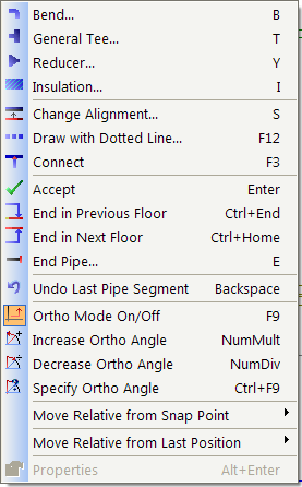
For other functions, press the right mouse button. A pop-up menu will then display:
|
The most important functions for pipe drawing are in the pop-up menu. Components like tees, reducers etc. can be inserted while the pipe is drawn. We would still recommend that you insert these components after having finished drawing the pipe.
Note the shortcut keys to the right of each command. B for bend, t for tee etc. will speed up your work more efficiently.
|
Bend
Change of direction is done with a bend. As previously mentioned, a bend in the horizontal plan can be done by pressing the left mouse button while drawing a pipe. If you want to go up or down, this is also done with a bend. Select bend with the command B on your keyboard, or from the pop-up menu (click the right mouse button). Dialog for bend holds information such as angle, radius and rotation. In the rotation field the absolute rotation is around the centre line of the bend.
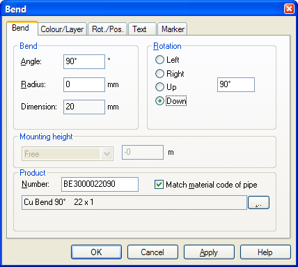
Dialog box for bend. Angle degrees, radius to the left, and new direction to the right.
Rotation to bend can be freely set with degrees from 0 to 360. Right is 0, down is 90, left is 180 and up is 270.
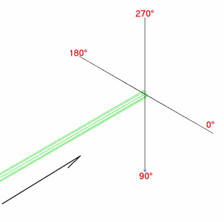
Rotation of bend according to drawing direction for the pipe.
See video how to define a left bend with 45 degrees twisted upwards – in the middle between 180 and 270 degrees. (=225 degrees)

Click to see a video
If you decide to go straight up or straight down, the dialog box asking for height will appear. This is the same dialog box as when you start a pipe from an object with a fixed direction, either up or down.
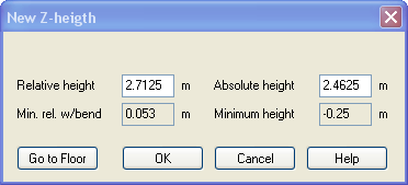
New height if bend up has been selected. My height is the point in which the pipe is positioned when bend is to be inserted.
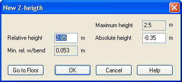
New height if bend down has been selected. Maximum height is the point where the pipe is positioned when bend is to be inserted.
As the pop-up menu displays, the keyboard can also be used to insert “nodes” up or down. Page Up and Page Down insert a bend up/down after having asked for the angle. Home and End goes directly to the question about a new height upwards or downwards.
ORTHO
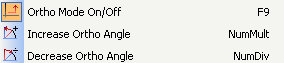
The ORTHO concept treats free angles for ”nodes”. If ORTHO is active, the angle will ”jump” in certain intervals. The intervals will differ according to the medium you are drawing. For instance, flexi pipes as pipe in pipe will operate with ORTHO off until you turn it on. ORTHO intervals are 30, 45, 60 and 90 degrees.
The function can either be turned on or off from the pop-up menu, or by pressing F9 on your keyboard.
Be aware, that with some pipe medium you must press F9 twice to get entirely free angles, as the angle interval is only half the first time you press F9.
If ORTHO is entirely free, turn it on again by pressing F9.
ORTHO option on pop-up menu.
Click to see a video
Undo
If you have inserted a ”node” you do not want, you can undo this from the pop-up menu by pressing Delete last line or point - Backspace
This will function when you have a dynamic pipe or an active line. After finishing the pipe this dialog will not function.
As displayed in the text in the pop-up menu, you can also press Backspace on your keyboard to undo points.

Undo last point from the pop-up menu.
Click to see a video
Insert components in existing pipes
After having drawn a pipe, components can be inserted. Components are found in the toolbox in the tools Pipes.
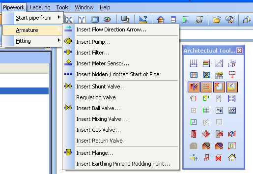
Where in the DDS menu to find components to be inserted into pipes.
First, select the component type from the menu, and then press the left mouse button on the pipe in which you want to insert the component.
If you want to insert a component in a vertical pipe, DDS will ask for component height.
In the example below, a valve is to be inserted in a vertical heating pipe
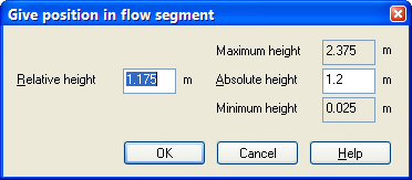
The dialog shows that a vertical pipe starts at height Z = 0.025 meter and ends at height Z = 2.375 meter. Between the heights you can enter the component in the field Absolute height.
Click to see a video
If you have a horizontal pipe, going vertical and them back to horizontal, you can be asked in which pipe you want to insert the component.
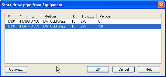
The example displays a horizontal pipe in height Z=0.400 meter, horizontal direction 270 degrees and vertical direction 0 degrees. Then a vertical part with horizontal direction 270 and vertical direction -90.
If you want to insert the component into the vertical pipe section (see the list field Vertical), DDS will ask on which height the component is to be inserted. It must possibly be entered under the flag ”Positioning”
< Previous Section - Next Section >